Detailed Laboratory Skills, Techniques, and Knowledge acquired
Research Projects
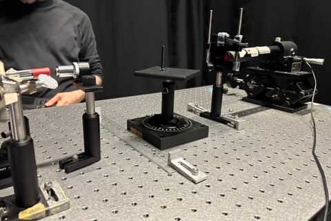
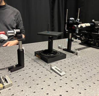
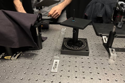
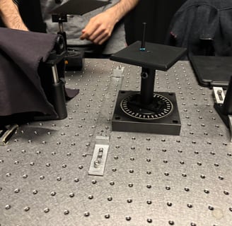
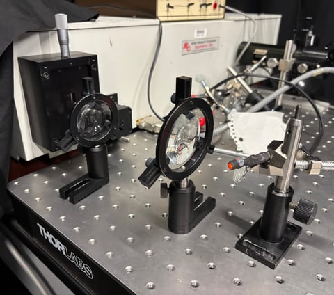
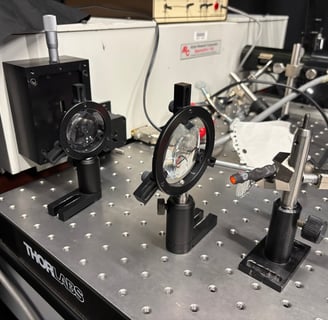
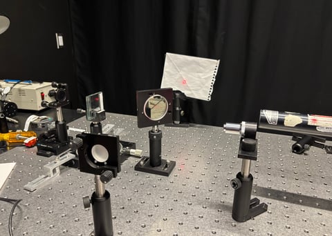
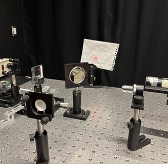
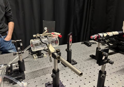
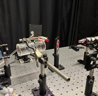
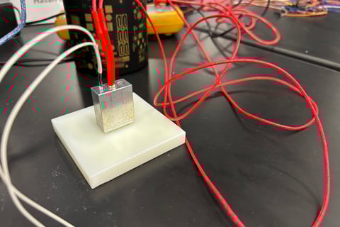
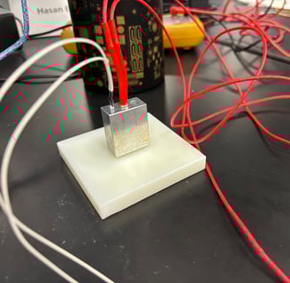
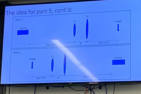
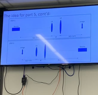
Project 1: Computed Tomography, A Proof of Concept (2025)
Computed Tomography Imaging: Constructed a first-generation CT scanner setup using visible light to generate 2D and 3D reconstructions of cylindrical and triangular prism samples.
Optical Setup Design: Aligned a HeNe laser (632.8 nm), convex lens, linear polarizers, and beam expander to optimize light detection with a photodiode
Data Acquisition: Manually collected light intensity data using LoggerPro software, accounting for angular and linear movements of samples.
Image Processing: Applied Simple Back Projection (SBP) and Filtered Back Projection (FBP) with a ramp filter using Python libraries (matplotlib, skimage, numpy).
Radon Transform Application: Utilized the Radon transform and projection-slice theorem to convert illumination data into sinograms for image reconstruction.
3D Modeling: Stacked 2D cross-sectional images to create 3D reconstructions of samples, improving resolution through data interpolation
Symmetry Utilization: Leveraged radial symmetry of cylindrical samples to reduce data collection time via interpolation.
Error Analysis: Quantified illumination measurement uncertainties (±0.5 to ±20 lux) based on light intensity conditions.
Opto-Mechanical Assembly: Secured components on an optical breadboard, using screws and clamps to stabilize the setup.
Problem Solving: Adapted the experimental design due to equipment limitations, incorporating a cloth to reduce ambient light noise and polarizers to prevent detector saturation.
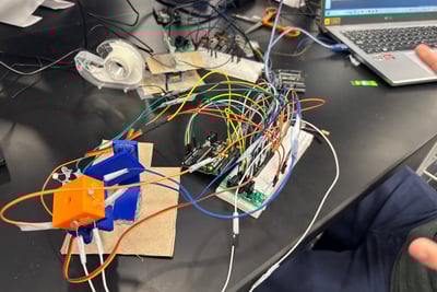
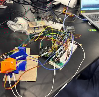
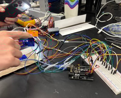
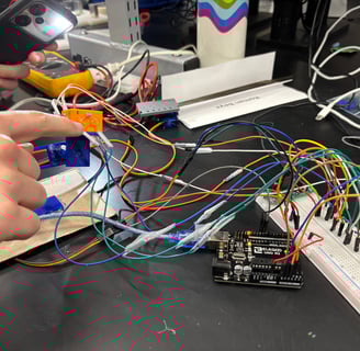
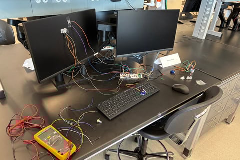
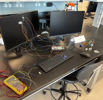
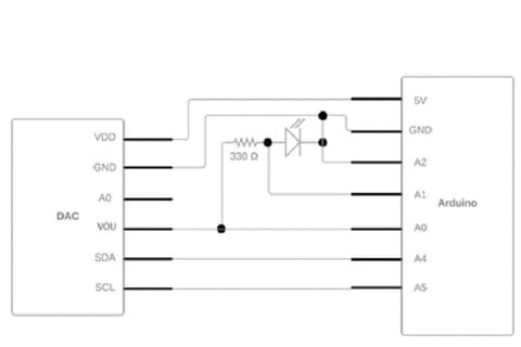
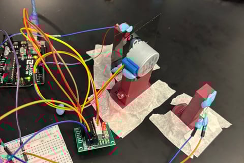
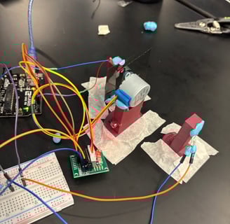
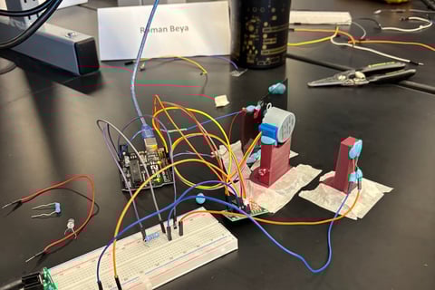
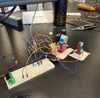
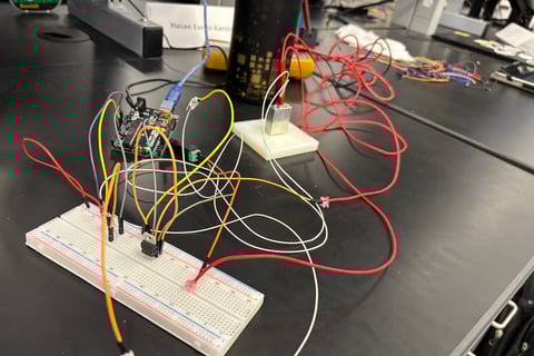
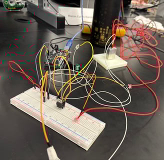
Project 2: Digital Sunflower using a Feedback Control System (2024)
Feedback Control Systems: Designed a real-time light-tracking system using LDR feedback to control servo motors.
Arduino Programming: Developed code with PWM for precise servo control and LDR voltage comparisons.
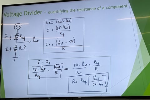
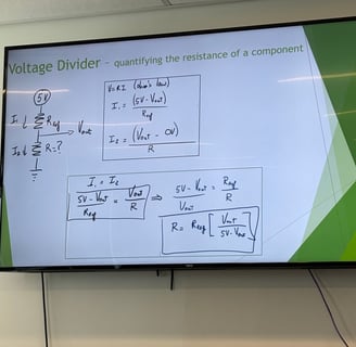
Circuit Design: Built and tested four-stage voltage divider circuits with LDRs for light detection.
Mechanical Design: Engineered a 3D-printed chassis with orthogonal servos for dualaxis motion.
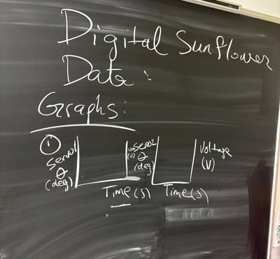
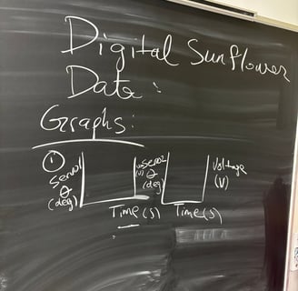
Data Acquisition: Measured LDR voltages and servo angles, logged via Arduino’s Serial Monitor.
Data Analysis: Used Python to plot sinusoidal LDR responses and validate light intensity gradients.
Optics Knowledge: Applied principles of electric flux and light intensity to interpret LDR behavior.
Problem-Solving: Overcame servo saturation, loose connections, and noise with software and hardware fixes.
Electronics: Soldered connections and resolved ground loop issues for stable circuit performance.
Technical Writing: Documented system design, results, and challenges in a comprehensive
report
Physics Labs
PHY 3904 - Physics and Applied Physics Laboratory II
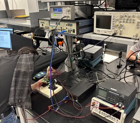
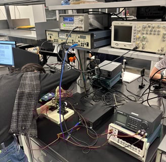
Experiment 1: Low-level Signal Detection, Exploring the Oscilloscope and The Lock-In Amplifier (LIA)
Signal Processing: Utilized lock-in amplifiers (SR510/SR530) to extract low-level signals from noisy environments.
Oscilloscope Operation: Configured Agilent DSO1012A oscilloscope for time-scale, XY, and FFT analysis to measure signal frequency and phase.
Circuit Configuration: Designed circuits with function generators, LEDs, speakers, and high-resistance loads for signal detection experiments.
Phase Measurement: Adjusted LIA phase settings to monitor phase shifts and calculate the speed of sound in air.
Noise Reduction: Employed optical choppers to modulate light signals, minimizing interference from stray light sources.
Low-Level Current Measurement: Used Keithley picoammeter and LIA to detect picoampere-level currents from LED receivers.
Data Acquisition: Monitored and recorded signals using oscilloscopes, digital multimeters, and LIA outputs.
Frequency Analysis: Applied function generators to produce modulated signals and analyzed frequency limits in sound experiments.
Error Analysis: Estimated uncertainties in speed of sound measurements and compared results with theoretical values.
Instrument Calibration: Set appropriate sensitivity scales and time constants on LIAs to avoid signal overloading.
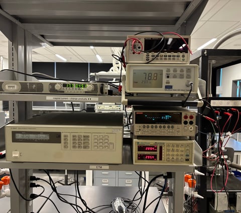
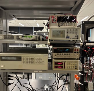
Experiment 2: Electrical Transport Measurements
Semiconductor Characterization: Measured resistivity and Hall voltage to determine band gap and charge carrier density in a semiconductor.
Hall Effect Measurement: Observed transverse voltage under magnetic fields to study charge carrier behavior.
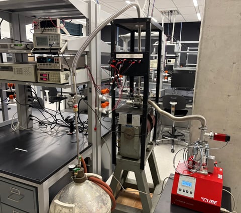
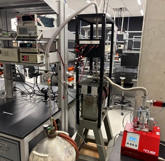
Cryogenic Techniques: Used liquid nitrogen (77.2 K) and a Janis Optical Cryostat for low-temperature experiments.
Vacuum Technology: Maintained a high vacuum (10 hPa) using a HiCube Pfeiffer Diffusion Pump for precise temperature control.
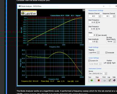
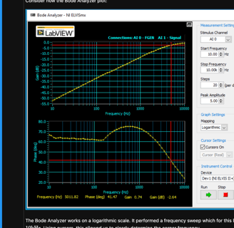
Data Acquisition: Configured NI LabVIEW with GPIB-to-USB interfaces for automated resistivity and voltage measurements.
Instrument Calibration: Calibrated a Platinum Resistor Thermometer (Pt-100) and Gaussmeter Probe for accurate temperature and magnetic field readings.
Circuit Design: Built and verified ohmic contacts using a DC power supply and Keithley 2700 multimeter, confirming Ohm’s Law.
Magnetic Field Generation: Operated electromagnets with iron cores to produce uniform fields up to 152.6 mT, applying safe voltage ramping.
Error Analysis: Identified anomalies in Hall voltage data due to loose contacts or wiring issues, proposing calibration improvements.
Solid State Physics: Applied band gap theory and Lorentz force principles to interpret exponential resistivity decay and Hall voltage trends.
Experiment 3: Light Spectroscopy
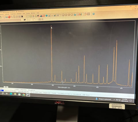
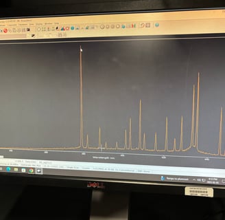
Light Spectroscopy: Recorded and analyzed emission spectra of Ne and Na lamps using a high-resolution spectrograph.
Detector Calibration: Calibrated CCD and Si PIN diode detectors with Ne lamp spectra across multiple diffraction gratings.
Spectral Analysis: Measured Na doublet wavelengths and compared with accepted values to assess grating resolution.
Optical Setup: Designed and built front optics to focus light onto the spectrograph’s entrance slit.
Low-Level Signal Detection: Used a Stanford Research SR510 lock-in amplifier to record low-level light signals in scanning mode.
Data Acquisition: Configured LabVIEW for automated spectral data collection and time-scale calibration.
Semiconductor Characterization: Determined band gap energy of a semiconductor through light absorption measurements.
Instrument Operation: Adjusted spectrograph slit widths to study effects on spectral linewidth and resolution.
Opto-Mechanical Assembly: Utilized optical breadboards and components for precise alignment in spectroscopy setups.
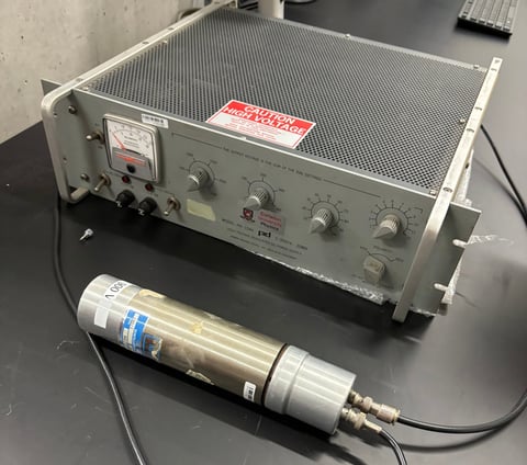
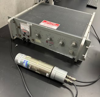
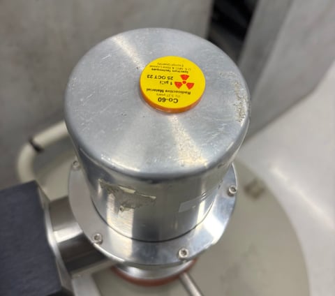
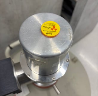
Experiment 4: Gamma-Ray Spectroscopy
Gamma-Ray Spectroscopy: Recorded and analyzed gamma-ray spectra using Ge and NaI(Tl) detectors with a multichannel analyzer.
Detector Calibration: Calibrated energy scales for Ge and NaI(Tl) detectors using radioactive sources and GENIE software.
Pulse Height Analysis: Performed pulse height analysis to interpret gamma-ray spectra and identify isotope-specific energy peaks.
Compton Scattering Analysis: Measured electron rest mass via Compton edge analysis, applying special relativity principles.
Radiation Safety: Handled radioactive sources and lead safely, adhering to protocols for high-voltage equipment and low-activity materials.
High-Voltage Electronics: Operated detectors at high voltages (up to +4500 V), ensuring gradual voltage adjustments to prevent damage.
Signal Processing: Adjusted pulse shaping times and amplifier settings to optimize peak shape and line resolution.
Background Radiation Analysis: Identified isotopes in background radiation spectra collected over extended periods.
Data Acquisition: Used oscilloscopes and multichannel analyzers to collect and store spectral data in .cnf and .tka formats.
Comparative Analysis: Compared Ge and NaI(Tl) detector performance in terms of efficiency, linewidth, and spectral resolution.
Experiment 5: Michelson Interferometry
Michelson Interferometry: Built and aligned a Michelson interferometer to measure light wavelengths and refractive indices.
Optical Alignment: Precisely aligned laser beams, beamsplitters, and mirrors using a He-Ne laser for optimal interference patterns.
Fringe Analysis: Counted interference fringes to calibrate digital indicators and measure optical path differences.
Refractive Index Measurement: Determined indices of refraction for glass and gases (air, argon, helium) via fringe shifts with rotation stages and gas cells.
Wavelength Determination: Measured the Na doublet wavelengths and their separation through beat pattern analysis.
Precision Instrumentation: Operated micrometric screws, picomotors, and digital gauges for sub-micron mirror adjustments.
Laser Safety: Applied laser safety protocols when handling He-Ne lasers and Na lamps.
Gas Handling: Safely managed high-pressure gas cylinders and hand pumps to control gas cell pressure.
Data Acquisition: Used computer interfaces to record fringe counts and pressure sensor data with uncertainty propagation.
Opto-Mechanical Setup: Assembled optical components on a breadboard, ensuring clean handling of delicate surfaces.
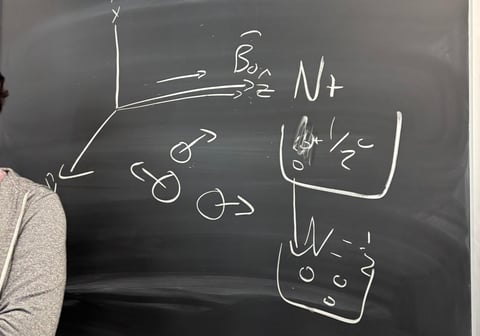
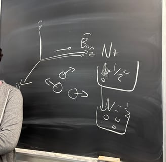
Experiment 6: Nuclear Magnetic Resonance (NMR)
Pulsed NMR Operation: Configured and operated a TeachSpin PS1-A spectrometer to generate RF pulses and detect NMR signals.
Pulse Sequence Design: Implemented Pi/2 and Pi pulse sequences to measure T1 and T2 relaxation times via FID and spin echoes.
Signal Detection: Used pickup coils and receiver circuits to observe FID and spin echo signals on an oscilloscope.
RF Electronics: Tuned 15 MHz oscillator and amplifier for precise RF pulse generation and minimized mixer beat frequencies.
Relaxation Time Measurement: Accurately measured T1 using the zero-crossing method and T2 via multipulse spin echo sequences.
Material Characterization: Analyzed T and T for samples (e.g., mineral oil, water, glycerine) to study spin dynamics.
Phase Transition Analysis: Investigated NMR signal changes in paraffin during solid-to-liquid phase transitions.
Doping Effects: Measured T1 and T2 variations in water with CuSO doping to study paramagnetic ion effects.
Diffusion Studies: Explored spin echo amplitude decay due to molecular diffusion in non-uniform magnetic fields.
Data Acquisition: Utilized oscilloscope cursor measurements and LabVIEW interfaces for precise time and voltage data collection.
PHY 3902 - Physics and Applied Physics Laboratory I
Experiment 1: Introduction to Data Acquisition with Arduino, Sensors, and Motors
Mastered the Arduino microcontroller platform, including its 10-bit resolution, pin functionality, and integration of various libraries in sketches for enhanced functionality.
Implemented an external LED fading circuit using a light-dependent resistor (LDR) and pulse-width modulation (PWM), demonstrating control over analog output.
Measured voltage across an LED using C code and the analogRead function, applying analog input techniques for precise sensor data acquisition.
Automated the Google Dinosaur game by designing a system with an LDR sensor and servo motor to detect obstacles and simulate key presses, showcasing sensor-actuator integration.
Optimized Arduino code and hardware setup to maximize performance in the Google Dinosaur game, achieving high scores through efficient programming and calibration.
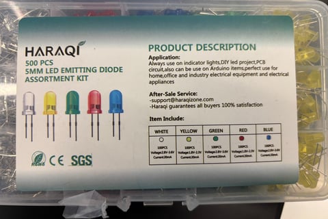
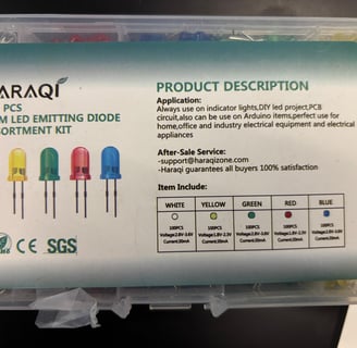
Experiment 2: Characteristics of Light-Emitting Diodes (LEDs)
Circuit Design: Built and analyzed voltage divider circuits with Arduino and DAC shield for LED testing.
Arduino Programming: Wrote sketches for voltage sweeps and data acquisition using analogRead().
Data Acquisition: Collected voltage/current data with uncertainties, exported to CSV.
Data Analysis: Performed curve fitting and linear regression with Python’s scipy and pandas.
Visualization: Created plots to visualize I-V relationships and threshold voltage trends.
Physics Application: Applied Planck-Einstein relation to estimate Planck’s constant.
Semiconductor Knowledge: Studied LED threshold voltages and wavelength-energy relationships.
Error Analysis: Calculated propagated errors for measurements and curve fits.
Technical Writing: Documented experimental methods, results, and conclusions in a lab report.
Problem-Solving: Adjusted regression ranges to account for varying LED threshold voltages.
Experiment 3: Characteristics of a Laser Diode
Optical Experiment Design: Configured setups to study laser diode polarization, reflection, and beam profiling.
Arduino Programming: Developed sketches for stepper and servo motor control and LDR data acquisition.
Data Acquisition: Measured voltage drops across LDR with averaging to reduce noise, exported to CSV.
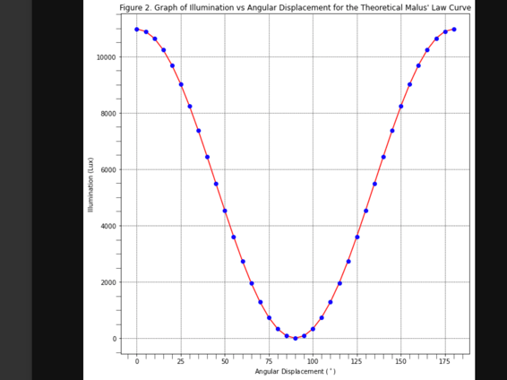
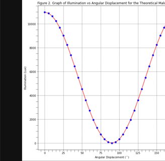
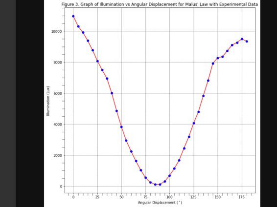
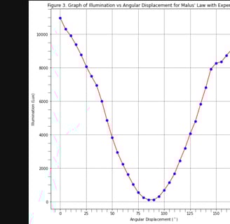
Data Analysis: Used Python to plot and fit data, verifying Malus’s Law and Brewster’s Angle.
Polarization Physics: Applied Malus’s Law and Fresnel equations to analyze light behavior.
Error Analysis: Calculated uncertainties from multiple measurements and identified calibration offsets.
Electronics: Implemented voltage divider circuits with LDRs for light intensity measurements.
Technical Writing: Co-authored a detailed lab report with clear methodology and results.
Problem-Solving: Mitigated noise with opaque enclosures and addressed servo motor limitations.
Optics Knowledge: Understood laser beam profiles and polarization effects in dielectrics.
Experiment 4: Servo Control Loops (Feedback Control Systems) – PID Temperature Controller
Feedback Control Systems: Implemented and compared Hysteresis, P, PI, and PID control for temperature regulation.
Arduino Programming: Wrote sketches to control heating elements and read thermistor data via MOSFET.
Circuit Design: Configured voltage divider circuits with thermistors for temperature measurement.
Data Acquisition: Collected temperature and power data, exported to CSV for analysis.
Data Analysis: Used Python to plot temperature responses and calculate specific heat capacity.
Thermal Physics: Measured aluminum’s specific heat capacity using energy transfer equations.
Error Analysis: Quantified uncertainties in specific heat capacity measurements.
Technical Writing: Documented control system performance and trade-offs in a lab report.
Problem-Solving: Tuned PID parameters to optimize stability and minimize oscillations.
Electronics: Integrated MOSFET for precise power control in heating applications.
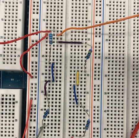
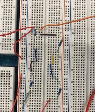
PHY 2104 - Introduction to Circuit Theory and Electronics
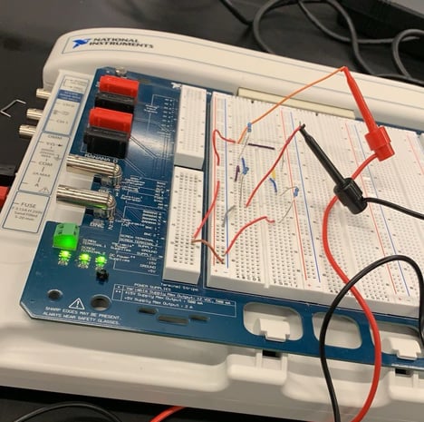
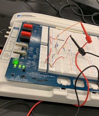
Experiment 1: Introduction to measurements with NI ELVIS II+ and data analysis using Python
DC Circuit Building: Constructed and troubleshot DC circuits on NI ELVIS II+ prototyping board, ensuring clean layouts and safe operation.
Electrical Measurements: Utilized virtual instruments (DMM, VPS, 2-Wire) to measure voltage, current, and resistance, characterizing resistors and LEDs.
Data Analysis: Analyzed I-V curves for resistors and diodes using a 2-Wire analyzer, determining resistance and diode offset voltage.
Ohmic Theory: Applied Ohm’s Law to verify component behavior and assess electrical safety risks.
Computation in Python: Performed data analysis and visualization in Python using Google Colab, numpy, scipy, and matplotlib, fitting linear models to experimental data.
Experiment 2: Equivalent Resistance and Introduction to AC measurements
Stability Measurements: Measured load characteristics of a variable power supply (VPS), analyzing voltage vs. current to assess source stability.
Equivalent Resistance: Determined equivalent resistance using Wheatstone bridge circuits,
comparing results with DMM measurements and color code estimates for accuracy.
Circuit Analysis Theory: Measured node voltages and mesh currents in DC circuits, applying circuit analysis techniques to verify theoretical values.
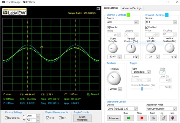
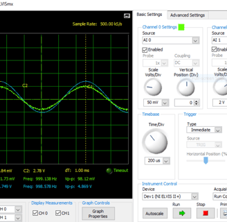
Building Testing AC circuits: Investigated AC circuit behavior with voltage dividers, rectifiers (using LEDs), and opposing LED pairs, analyzing signal shapes and amplitudes at varying frequencies (1 Hz to 250 kHz).
Semiconductor Concepts: Characterized rectifier circuits, measuring input/output peak-to-peak voltages and identifying threshold voltages for LEDs.
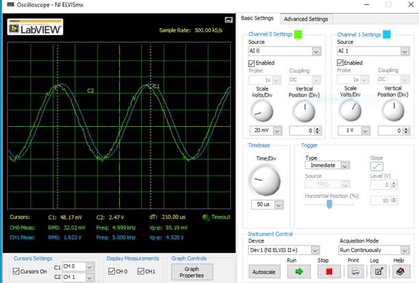
Experiment 3: Operational Amplifiers
Variable Gain Amplifier Design: Mastered the construction and testing of both inverting and non-inverting operational amplifier circuits with adjustable gain using potentiometers and precision resistors.
Frequency Response Analysis: Developed proficiency in characterizing op-amp performance across frequency ranges (1-10 kHz), measuring phase shifts and gain variations using oscilloscope techniques.
Saturation Voltage Characterization: Acquired expertise in determining op-amp saturation limits under varying supply voltages (±8V to ±10V), understanding dynamic range limitations.
Gain-Bandwidth Product Measurement: Gained skills in evaluating comparative performance between LM741 and LF356 op-amps, calculating cutoff frequencies and bandwidth characteristics.
Error Propagation Analysis: Mastered uncertainty calculations for electronic measurements,
applying statistical methods to assess measurement accuracy and validate experimental results.
Circuit Troubleshooting: Developed diagnostic skills in identifying faulty components (defective op-amps), implementing component replacement, and verifying circuit functionality.
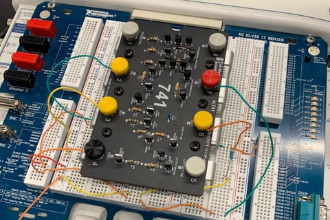
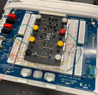
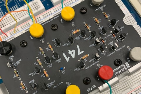
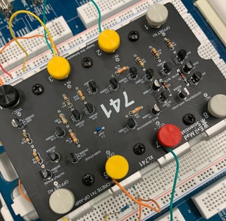
Experiment 4: Building and Testing a Discrete Operational Amplifier
Soldering Techniques: Developed hands-on soldering skills for electronic components and PCB assembly, constructing a complete discrete operational amplifier circuit.
Inverting Amplifier Configuration: Gained proficiency in building and testing inverting amplifier circuits with variable feedback resistances, analyzing gain characteristics and circuit behavior.
Electronic Measurement Techniques: Acquired expertise in voltage and current measurements using laboratory instrumentation to characterize op-amp performance and validate circuit functionality.
Op-Amp Ideality Assessment: Mastered evaluation of operational amplifier characteristics including input current analysis and deviation from ideal behavior.
Circuit Analysis and Validation: Developed skills in systematic data collection, gain calculations, and linearity assessment for analog electronic circuits.
Laboratory Setup: Configured test equipment and measurement systems for precise characterization of discrete operational amplifier performance across multiple operating conditions.
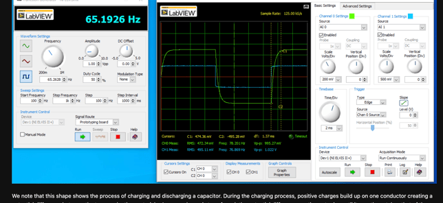
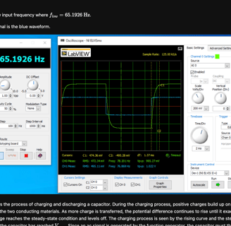
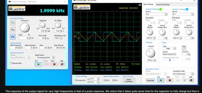
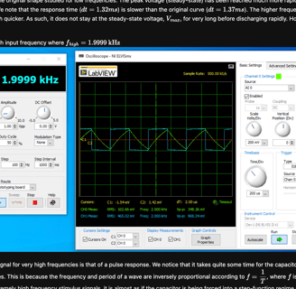
Experiment 5: Transient Response of First-Order RC and Second-Order RLC Circuits
Time Constant Measurement: Mastered characterization of first-order RC circuits with varying capacitance values (47 nF to 0.47 μF), measuring transient response times and maximum frequency behavior.
Op-Amp Integrator Analysis: Developed proficiency in constructing and testing both ideal and practical op-amp integrator circuits, analyzing DC offset effects and signal integration for sinusoidal and square wave inputs.
Second-Order System Characterization: Gained expertise in analyzing RLC circuit damping behaviors including under-damped, critically-damped, and over-damped responses through systematic resistance and capacitance variation.
Oscillation Period Analysis: Acquired skills in measuring oscillation periods and cycle counting for under-damped systems, correlating damping coefficient changes with circuit component values.
Frequency Response Testing: Mastered evaluation of circuit behavior across frequency ranges, identifying maximum operating frequencies and high-frequency roll-off characteristics.
Transient Signal Analysis: Developed expertise in using oscilloscope techniques to capture and analyze transient waveforms, measuring rise times, settling behavior, and steady-state responses in reactive circuits.
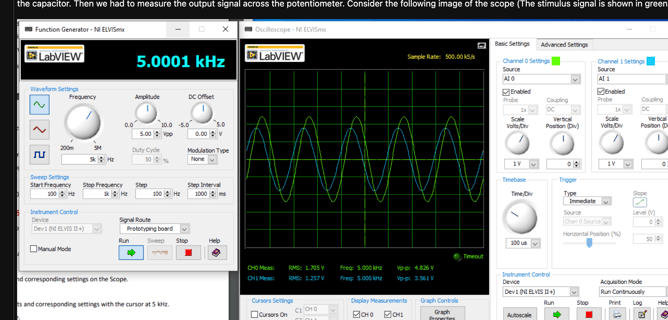
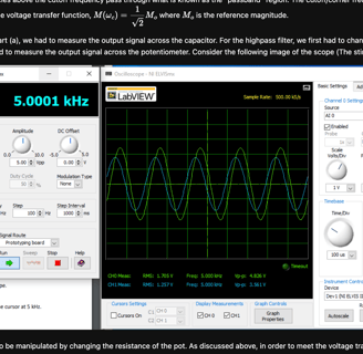
Experiment 6: Filters and Transfer Functions
Filter Circuit Design: Mastered construction and analysis of first-order RC filter circuits with varying capacitance values, characterizing low-pass and high-pass filtering behaviors across frequency ranges.
Transfer Function Analysis: Developed proficiency in measuring and analyzing transfer functions of electronic filters, determining cutoff frequencies and frequency response characteristics through systematic testing.
Active Filter Implementation: Gained expertise in designing op-amp based active filters, comparing ideal versus practical integrator performance with sinusoidal and square wave inputs.
Second-Order Filter Characterization: Acquired skills in analyzing RLC filter circuits, measuring quality factors, resonant frequencies, and damping effects through component variation techniques.
Frequency Domain Measurements: Mastered use of oscilloscope and function generator for frequency sweep analysis, measuring amplitude and phase responses across multiple decades of frequency.
Filter Performance Evaluation: Developed techniques for assessing filter selectivity, roll-off rates, and passband characteristics, correlating theoretical predictions with experimental measurements.
PHY 2311 - Waves and Optics
Experiment 1: Wave Simulations in Python
Python Programming: Gained proficiency in using Python libraries (Matplotlib, NumPy) for mathematical operations, loops, and plotting static and dynamic graphs in physics simulations.
Harmonic Wave Simulation: Learned to simulate a harmonic wave (ψ(x) = Acos(kx)) with given parameters (λ = 6 cm, A = 2 cm), plotting over three cycles with Δx = 0.1 cm.
Beat Signal Analysis: Developed skills in simulating beat signals from two harmonic waves, deriving and plotting their superposition over five cycles.
Standing Waves Modeling: Mastered modeling standing waves on a string (L = 16 cm) from two counter-propagating harmonic waves, calculating harmonic mode wavelengths and frequencies.
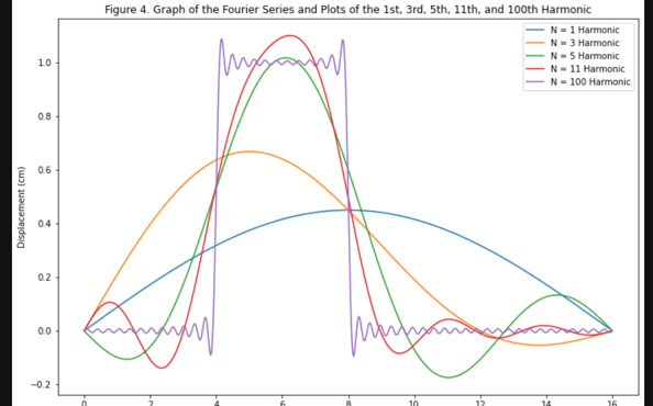
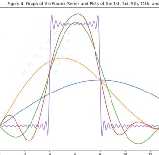
Fourier Analysis: Learned to apply Fourier theorem to represent a square pulse as a sum of harmonic modes, computing Fourier coefficients simulating for varying harmonic terms (N = 1, 3, 5, 11, 100).
Gaussian Wave Packet Animation: Acquired expertise in simulating and animating a Gaussian wave packet at multiple time points and over a 1-minute interval.
Data Visualization: Enhanced ability to create clear, accurate plots for wave phenomena, including static graphs for harmonic modes and dynamic animations for wave propagation
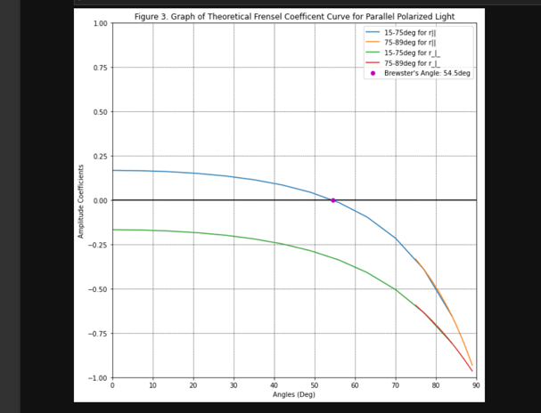
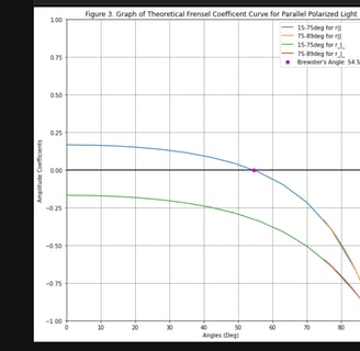
Experiment 2: Fresnel Reflection
Fresnel’s Equations: Mastered the use of Fresnel’s equations for reflection coefficients to analyze light reflection at air-dielectric interfaces.
Brewster Angle Determination: Gained proficiency in measuring the Brewster angle (tan θB = n) to determine the refractive index of a material, where parallel-polarized light reflection is zero.
Polarization Effects: Learned to measure reflection coefficients for parallel (∥) and perpendicular (⊥) polarizations over a range of incidence angles (15° to 75°), using a diode laser and silicon photocell.
Experimental Setup: Developed skills in configuring an optical system with a prism table, polarizer, and photocell circuit to accurately measure reflected light intensity and angles.
Data Analysis: Acquired expertise in plotting reflection coefficients versus incidence angle, comparing results with Fresnel’s predictions.
Surface Quality Control: Understood the importance of maintaining clean, scratch-free reflecting surfaces to ensure accurate measurements, addressing potential sources of error.
Safety Practices: Learned to safely handle diode lasers, avoiding direct beam exposure and using paper to view beam images.
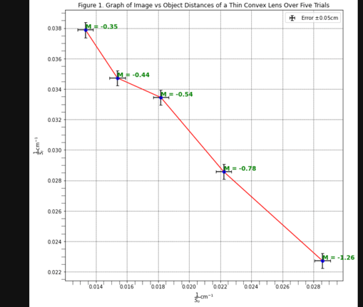
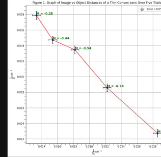
Experiment 3: Geometrical Optics - Lens Systems
Lens Equation Application: Mastered the thin lens equation to determine
focal lengths and image distances for single and compound lens systems.
Focal Length Measurement: Gained proficiency in measuring focal lengths of converging
lenses using three methods: (a) graphing (b) displacement method for fixed object-image distance L > 4f, and (c) self-conjugate point method with a pin and mirror.
Diverging Lens Analysis: Learned to measure the focal length of a diverging lens by analyzing the shift in image position when combined with a converging lens, using the lens equation with virtual object distances.
Compound Lens Systems: Developed skills in analyzing two-lens systems, calculating effective focal length, and focal point positions.
Telescope Construction: Acquired expertise in constructing and characterizing astronomical and Galilean telescopes, estimating magnification visually and comparing with theoretical values based on focal lengths.
Laser Beam Expansion: Learned to use a telescope as a laser beam expander, measuring beam expansion and validating results with calculations from lens focal lengths.
Experimental Validation: Enhanced ability to compare experimental measurements of focal lengths and focal point positions with theoretical predictions, assessing optical system performance.
Experiment 4: Polarization
Polarization Concepts: Learned the nature of light as a transverse wave, distinguishing linear, circular, and elliptical polarization based on electric field vector behavior.
Malus’s Law Verification: Gained proficiency in demonstrating Malus’s law by measuring transmitted light intensity through polarizer-analyzer pairs at varying angles.
Brewster Angle Measurement: Developed skills in determining the Brewster angle (tan iB = n) for complete polarization of reflected light, using reflection from a dielectric surface.
Circular Polarization Production: Mastered producing and verifying circularly polarized light using a quarter-wave plate, observing phase differences (ϕ = π
2 ) in birefringent crystals.
Photoelasticity Observation: Learned to observe birefringence in strained plastics between crossed polarizers, understanding stress-induced optical anisotropy.
Photocell Calibration: Acquired expertise in calibrating a photocell with a sodium lamp and neutral density filters, plotting current versus light intensity.
Experimental Setup: Developed skills in configuring optical systems with polaroids, quarter-wave plates, and photocells to measure polarization effects accurately.
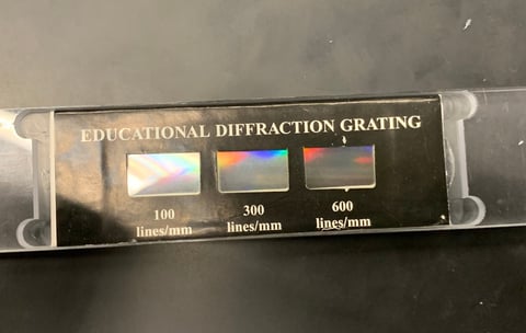
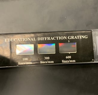
Experiment 5: Diffraction and Interference
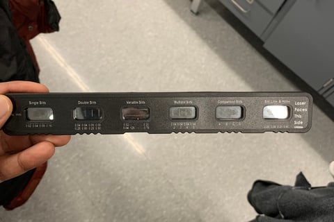
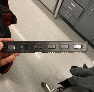
Diffraction Theory: Learned Fraunhofer diffraction principles for single slits, double slits, diffraction gratings, and circular apertures, understanding intensity distribution formulas.
Single Slit Diffraction: Gained proficiency in measuring diffraction patterns from a single slit using a He-Ne laser (λ = 632nm), calculating slit width from angle measurements.
Double Slit Interference: Developed skills in analyzing double-slit diffraction-interference patterns, determining slit width and separation from measured intensity distributions.
Diffraction Grating Analysis: Mastered measuring grating constants by analyzing diffraction patterns, using angle measurements derived from distances on a viewing screen.
Circular Aperture Observation: Acquired qualitative understanding of diffraction patterns from circular apertures, observing Airy disk patterns.
Experimental Techniques: Learned to use a He-Ne laser and optical bench to project diffraction patterns, calculating angles via geometric measurements (distance ratios).
Safety Protocols: Understood safe laser handling, avoiding direct beam exposure using paper to view diffraction patterns.
PHY 2361 - Modern Physics
Experiment 1: Planck’s Constant
Photoelectric Effect: Learned Einstein’s photon theory, explaining photoemission properties (threshold voltage dependence on frequency, not intensity) via energy conservation (hf = eϕ + 1/2mv2).
Experimental Setup: Gained proficiency in using a mercury lamp, direct vision prism, photocell, picoammeter, and voltmeter to measure threshold voltages for visible wavelengths
(460–635 nm).
Threshold Voltage Measurement: Developed skills in determining threshold voltages by plotting picoammeter current versus applied voltage, identifying slope changes to account for thermal and back-current effects.
Planck’s Constant Determination: Mastered plotting threshold voltage versus frequency
(f = c/λ) to derive Planck’s constant h from the slope h/e.
Optical System Handling: Learned to configure an optical system with lenses and slits to minimize anode photoemission and filter harmful UV radiation from the mercury lamp.
Data Analysis: Acquired expertise in interpreting current-voltage graphs, using tangent intersection methods to estimate threshold voltages accurately
Safety Practices: Understood the importance of avoiding direct exposure to UV radiation and handling sensitive picoammeter circuits carefully.
Experiment 2: Electron Diffraction
Wave-Particle Duality: Learned de Broglie’s hypothesis (λ = h/p ) and its confirmation through electron diffraction, as demonstrated by Davisson-Germer and G.P. Thompson
Bragg’s Law Application: Gained proficiency in applying Bragg’s law (2d sin θ = nλ) to analyze electron diffraction patterns from graphite’s crystal lattice.
Experimental Apparatus: Mastered operating an electron diffraction tube with a 5 keV electron gun, graphite target, and phosphor screen, observing ring patterns.
Measurement Techniques: Developed skills in measuring diffraction ring diameters
D at varying voltages (3–5 kV) and using small-angle approximations (sin 2θ ≈ D2L) to calculate interplanar spacings.
Graphite Lattice Analysis: Understood graphite’s hexagonal lattice structure (unit cell: a = 2.456˚A, c = 6.79˚A) and identified planes responsible for observed diffraction rings.
Safety Protocols: Learned to handle high-voltage (5 kV) equipment safely, protect the fragile graphite target by limiting beam current (< 0.2 mA), and use plastic calipers to avoid bulb implosion.
Data Interpretation: Acquired expertise in comparing measured interplanar spacings with theoretical values to validate de Broglie’s wavelength predictions.
Experiment 3: Frank-Hertz
Energy Quantization Evidence: Learned the historical significance of the Frank-Hertz experiment in confirming atomic energy quantization, as predicted by Bohr’s model.
Experimental Setup: Gained proficiency in setting up a mercury-vapor tube with a heated cathode, anode, and collector, measuring collector current with a picoammeter.
Collision Dynamics: Understood elastic and inelastic electron-atom collisions, observing current drops when electron energy matches mercury’s excited state (2537 ˚A photon emission).
Temperature Control: Developed skills in operating a thermostatic oven to maintain mercury vapor pressure at 150–180°C, avoiding temperatures above 250°C.
Data Collection: Mastered plotting collector current versus anode voltage, identifying multiple peaks and minima corresponding to successive inelastic collisions.
Data Collection: Mastered plotting collector current versus anode voltage, identifying multiple peaks and minima corresponding to successive inelastic collisions.
Safety and Circuit Handling: Acquired expertise in managing high-voltage circuits, shielding collector connections, and preventing plasma discharge by limiting anode voltage.
Experiment 4: Spectroscopy
Spectroscopy Fundamentals: Learned the principles of analyzing materials via absorption, reflection, or emission spectra, focusing on the emission spectra of low-pressure gases excited by electrical discharge.
Grating Spectrometer Calibration: Gained proficiency in calibrating a spectrometer using the sodium line spectrum and the grating equation d sin θ = mλ, identifying first-order diffraction lines.
Emission Spectra Measurement: Developed skills in measuring emission wavelengths of hydrogen (H) and other gases (He, Ne, Hg, or N2), comparing results with tabulated values.
Rydberg Constant Determination: Acquired expertise in calculating the Rydberg constant R from hydrogen spectral lines for n = 3, 4, 5.
Molecular Spectra Observation: Understood the continuous rotational-vibrational spectra of molecular gases like N2 due to closely spaced quantum mechanical energy levels.
Molecular Spectra Observation: Understood the continuous rotational-vibrational spectra of molecular gases like N2 due to closely spaced quantum mechanical energy levels.
Reference Utilization: Enhanced ability to consult optics textbooks (e.g., Fowles, Jenkins and White, Hecht and Zajec) for theoretical background before experimentation.
Experiment 5: Cosmic Microwave Background
CMB Fundamentals: Learned the physical properties and origin of the Cosmic Microwave Background (CMB) radiation, formed 370,000 years post-Big Bang during recombination.
Planck’s Model Application: Understood Planck’s blackbody radiation model and its relevance to CMB energy density as a function of wavenumber and
temperature.
Data Fitting with Python: Gained proficiency in using Python packages (e.g., SciPy) to fit experimental CMB data to Planck’s model, optimizing for Planck’s constant with known temperature.
Temperature Estimation: Developed skills in fitting CMB data with known h to determine the cosmic background temperature, validating theoretical predictions.
Error Estimation: Learned to estimate standard errors in fitted parameters (h and T) using statistical methods, assessing the reliability of results.
Scientific Reporting: Enhanced ability to structure a lab report with sections on CMB discovery, properties, Planck’s model, Python tools, data analysis, and conclusions on model validity.
Data Interpretation: Acquired expertise in analyzing satellite-collected CMB data, linking electromagnetic energy density to temperature and frequency.
There’s more where that came from
Explore the skills I learned during my Chemistry labs!
Get in touch!
I would love to hear from you. If you have any questions, comments, or would like to work with me, please don't hesitate to reach out!